Overhead power transmission line fault indicator (OFI) is intended to determine the path of the short-circuit current through the overhead line 3-35 kV. It is recommended to install OFI on the taps of the power transmission line or at a certain distance (on long lines), which makes it possible to identify the damaged part of the network and reduce the time to search for a fault location.
Aftersales service
ISO 9001
in eqipment selection
Trainings
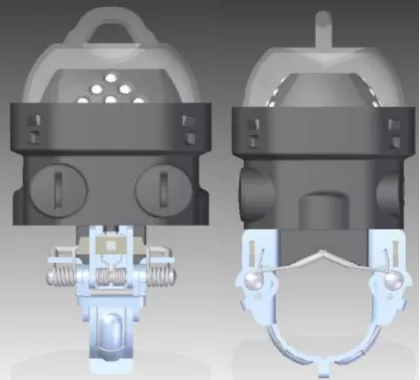
- Installation and demounting of devices can be carried out on a live line using a specialized installation kit, which can be supplied together with OFI. The outer diameter of the conductor is no more than 42 mm.
- Indicator housing is completely waterproof, shockproof; the mechanism for attaching to the line is made of stainless materials.
- Indicator housing is shockproof. The indicator is not damaged when dropped to the ground from a height of up to 10 m.
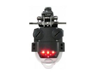
- For the convenience of night observation, a flashing light alarm is provided. There is a possibility of checking the operability of the device with the help of a magnet.
- It is possible to check the performance of the device using a magnet.
- Device is powered by long-life batteries (the batteries provide the device in standby mode for up to 8 years).
- Device monitors the battery charge status, and battery replacement is also provided.
- Recommended maintenance period is at least once every 3 years.
Installation and demountling of the OFI is carried out on an overhead power line without removing the voltage. The indicator is attached to the mounting cup, which is screwed onto the operational insulating rod using a threaded tip.
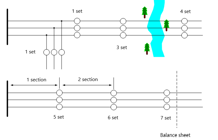
Indicators are installed at the fork of the power line, before and after hard-to-reach sections, at the border of the balance sheet, as well as after a certain distance along long sections.
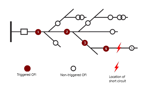
Indicator fixes the path of the short circuit current. When triggered, the OFI activate a flashing red (stable fault) or blue (unstable fault) LED indication, which provides a quick search for triggered indicators during the day and at night. Place of damage is located between the last worked and the first non-worked OFI from the power source. The return of the device can be carried out by time, by restoring the line, as well as manually.
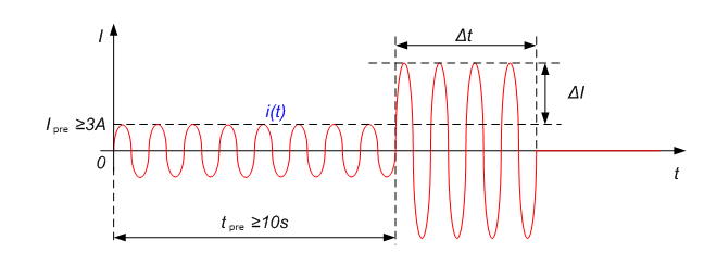
OFI distinguishes between the type of damage: short circuit or single-phase earth fault. In the event of a short circuit in the controlled section, the fault indicator responds to a current surge of more than 120 A, followed by a drop in current and voltage to zero. The operation of the connection switch is monitored by the current drop to zero. According to its principle of operation, the OFI does not work during load current surges, magnetizing current inrush, external short circuits. In the event of an external short circuit, the damaged section is switched off by an adjacent switch, the load current will continue to flow along the line, and the OFI will not operate. When installing OFI on a lightly loaded line (the load current of which does not exceed 3 A), a phase voltage measuring element is used to highlight the pre-emergency mode.
In addition to the differential, the device has a threshold current element. The operating range of the threshold current element is from 100 A to 650 A in steps of 10 A.
OFI distinguishes between permanent and intermitent fault. If the line is restored before the expiration of the time Tstab, OFI signals an intermitent fault, otherwise it indicates a permanent fault.
OFI is capable of detecting single-phase earth fault when a short circuit shunting device is installed at the supply substation. In the event of a single-phase earth fault, the short circuit shunting device briefly increases the current in the damaged phase by 30-50 A, which leads to the operation of the OFI.
OFI is powered by batteries with a long service life (batteries ensure the operation of the device in standby mode for up to 8 years). Each indicator is equipped with an internal battery charge diagnostic system. In case of battery discharge, the yellow LED alarm is activated. Replaceable indicator batteries are provided.
OFI includes a radio transmitter for transmitting information about the fact of operation and the type of damage to the control room. In this case, a transmitter is mounted on a support near the OFI installation, which, having received information from the OFI, retransmits it via the GSM communication channel. To save battery life of the OFI, the data transfer option can only be activated if transmitters are used.
|
Parameter |
Description | Value |
| Operating conditions | Operation temperature range | –40°…+80°С |
| Overhead line and system parameters | Electric line voltage | ≤ 35 kV |
| Line operating mode | Dead-end / Radial | |
| Minimum load current | 0 A | |
| Maximum load current | 600 A | |
| Minimum current surge under short circuit/single-phase earth fault | 120 А / 20 А | |
| Maximum time for switching off the section from protection | 10 s | |
| Wire diameter | 10 - 42 mm | |
| Types of detected faults |
- short circuit between phases, three-phase fault, double earth fault; - single-phase earth fault |
|
| Device options | Operational power supply |
- 7,2 V (2 replaceable batteries ER17505M 3,6 V / 3,2 Ah); - from line current |
| Working characteristics |
- differential current element (inverse current characteristic: ∆I = 160 A ~ 0.2 s; ∆I = 600 A ~ 0.02 s); - threshold current element (100 ÷ 650 A) |
|
| Minimum duration of the emergency process | 20 ms | |
| Flashing indication |
12 LEDs: - 6 red LEDs for permanent fault indication; - 4 blue LEDs for intermittent fault indication; - 2 yellow LEDs for low battery indication |
|
| Reset methods | by time / manually / by restoration of overhead lines | |
| Reset time | 2, 4, 6, 8, 10, 12, 24, 48 h | |
|
Duration of disconnected state of the line after the occurrence of a fault (for fixing permanent and intermittent faults) |
1 ÷ 20 min, step 1 min | |
| Maximum permissible current | 31,5 kA / 2 s | |
| Weight | < 0,5 kg | |
| Radio frequency | 433 MHz | |
| Radio transmission distance | up to 25 m | |
| Dimensions |
Ø 87 х 174 mm |

